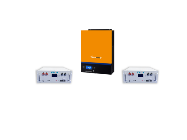
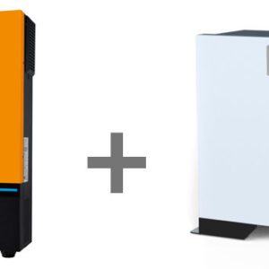
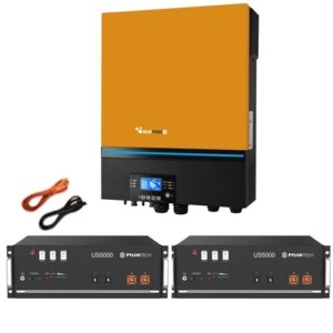
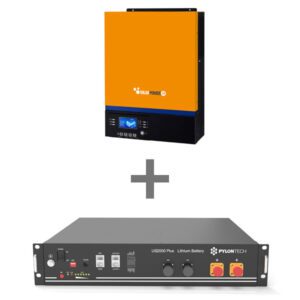
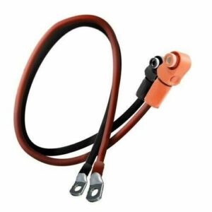
Kit SP24 Axpert VM III 5.0Kw 48V Off-Grid Inverter and 1 x Yilink 100AH 48V Batteries Total 4.8Kw Storage
€1.485,00
- Description
- Additional information
Description
Kit SP24 Axpert VM III 5.0Kw 48V Off-Grid Inverter and 1 x Yilink 100AH 48V Batteries Total 4.8Kw Storage
SP24 Axpert Primo VM III (PF1) 5Kw 48 Volt 5000-48 Off-Grid Island Solar Inverter
MAIN FEATURES
• Alternating Current Power 5kw
• Installable power 5kw panels
• 48V battery pack support
• Removable LCD control module with multiple communications
– Built-in Bluetooth for mobile monitoring (Android app is available)
• Supports USB On-the-Go function
– Reserved communication port for BMS RS485
– Battery management by SOC (state of charge) %.
• Replaceable fan design for ease of maintenance
• Supply the load from the grid or the PV, even if the battery is not available
• Use timer and priority of AC / PV configurable outputs
• High power selectable charging current
• Selectable input voltage range for household appliances and personal computers
– Compatible with mains power or generator input
• Automatic restart while AC is recovering
• Cold start function
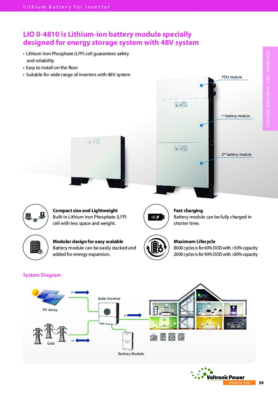
Yilink batteries 100AH 48V total 4.8Kw
Main features Battery
|
No.
|
Items
|
General Parameter
|
Remark
|
|
|
1 |
Combination method |
15S |
|
|
|
2 |
Nominal Voltage |
48V |
|
|
|
3 |
Rated Capacity |
Typical |
100Ah |
|
|
Minimum |
100Ah |
|||
|
4 |
Energy |
4800Wh |
|
|
|
5 |
Factory Voltage |
48 ~ 51V |
Mean Operation Voltage |
|
|
6 |
Voltage at end of Discharge |
37.5 ~ 42V |
Discharge Cut-off Voltage |
|
|
7 |
Voltage at end of Charge |
52.5 ~ 55.5V |
Charge Cut-off Voltage |
|
|
8 |
Standard charge |
Constant Current 20A Constant Voltage see No.7 0.02CA cut-off |
Charge time: Approx 5 ~ 6h |
|
|
9 |
Limiting current |
20A |
BMS Limited (Charge current is ≥100A to open the current Limit) |
|
|
10 |
Standard discharge |
Constant current : 20A end voltage see NO.6 |
|
|
|
11 |
Maximum Continuous Charge Current |
100A |
50ºC≥T≥5ºC |
|
|
12 |
Maximum Continuous Discharge Current |
100A |
55ºC≥T≥0ºC |
|
|
13 |
Operation Temperature Range |
Charge: 0 ~ 55 ℃ |
60 ± 25% RH No matter what mode the battery is in, once the temperature is found to exceed the absolute temperature range, stop charging or discharging immediately |
|
|
D.theschtorgAnd:–20~60℃ |
||||
|
14 |
Storage Temperature Range |
Less than 6 months: -10 ~ 35 ℃ |
60 ± 25% RH at the shipment state |
|
|
Less than 3 months: -10 ~ 45 ℃ |
||||
|
Less than 1 months: -20 ~ 55 ℃ |
||||
|
15 |
Dimensions (W * D * H) |
442 * 480 * 178mm |
I n c l u d e c a s e |
|
|
16 |
Net Weight |
46Kg |
I n c l u d e c a s e |
|
|
17 |
THEntAndrntoL THEmpAnddtoncAnd |
≤45 m Ω |
THEntAndrntoL rAndsthesttoncAnd mAndtosurAndd tot TOC. 1KHZ after 50% charge. The measure must uses the new batteries that within one week after shipment and cycles less than 5 times. |
|
Battery Management System
|
Function
|
||
|
Alarm |
Cell over-charge voltage |
Cell charge low temperature |
|
Cell over-discharge voltage |
Cell charge over temperature |
|
|
Pack over-charge voltage |
Cell discharge low temperature |
|
|
Pack over-discharge voltage |
Cell discharge over temperature |
|
|
Over-current charge |
Environment low temperature |
|
|
Over-current discharge |
Environment over temperature |
|
|
Mos over temperatures |
|
|
|
Protection |
Cell over-charge voltage |
Cell charge over temperature |
|
Cell over-discharge voltage |
Cell discharge low temperature |
|
|
Pack over-charge voltage |
Cell discharge over temperature |
|
|
Pack over-discharge voltage |
Environment low temperature |
|
|
Over-current charge |
Environment over temperature |
|
|
Over-current discharge |
Short circuit |
|
|
Mos over temperatures |
Fault |
|
|
Cell charge low temperature |
|
|
|
Others |
Cell balance function |
|
|
Communicate function |
||
|
Total capacity function |
||
|
Storage history function |
||
|
Current limiting function |
||
|
Dry contact function |
||
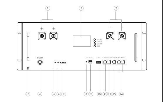
|
No.
|
Items
|
Description
|
|
1 |
+ Power terminal |
Power cable terminals: one connect to equipment, the other one paralleling to other battery module for capacity expanding |
|
2 |
– Power terminal |
|
|
3 |
LCD Screen |
Display the battery’s data |
|
4 |
Power Switch |
To turn ON / OFF while battery |
|
5 |
Working indicator light |
Display state information |
|
6 |
ALM alarm indicator light |
Red-trouble-light on |
|
7 |
Capacity volume indicator |
Display the battery’s capacity |
|
8 |
Reset Key |
Sleep / Activation / Reset |
|
9 |
ADS Dialer |
4 ADD switches, to define different address code for each battery module when multiple modules are cascaded, up to 15 addresses. |
|
10 |
Dry Contact Terminal |
1/2 No.orrmtoLLy orpAndn, cLorsAndd durtheng ftouLt prortAndcttheorn; 3/4 Normally open, closed when a low battery alarm |
|
11 |
RS485 |
RJ45 Port, used to connect to the inverter’s RS485 port |
|
12 |
CAN |
RJ45 Port, used to connect to the inverter’s CAN port |
|
13 |
RS232 |
RJ11 Port, used battery condition monitoring or manufacturer to debug or service |
|
14/15 |
RS485 |
RJ45 Port, used communication in parallel |
|
16 |
Grounding Point |
Safety |
.
The product can be sold with VAT reduced to 10% exclusively to Italian residents with shipping to Italy. In case of foreign customers, the site will recalculate according to the vat rate of the destination country
THE FORM YOU CAN FIND HERE
https://www.cercastock.it/repository/_barba_srl_dich_10.pdf
THE PRODUCT CANNOT BE SHIPPED UNTIL THE COMPLETED FORM IS RECEIVED
AT EMAIL ADDRESS moduloiva@solarpower24.it or by fax at 0545030125

